… another guest post by Greg (aka uncle Greg)
June 9th
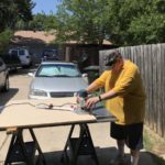
On the second Saturday in June Ben and I started the millwork … IN THE TEXAS HEAT!
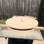
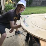
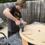
We set up our work area in the driveway on a couple pair of sawhorses with plywood tops. The first step was to install the router’s circle template hub which would be our source of truth for much of the millwork.
Once the hub was locked in, the clock face was cut from the 40″ square MDF blank to a final diameter of 38″. An 1/8″ straight bit and several passes – increasing the depth each – time made rather quick work of it.
We’re using my 2-1/4 horse power Bosch plunge router for the bulk of the work. Insert a big Tim the Toolman grunt here.
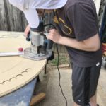
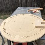
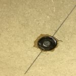
We also cut the inner ring with a 1″ bowl cutting bit. It definitely adds some interest to the face. Again the circle guide makes this a breeze. (Although the divot was the one “oops” I made.)
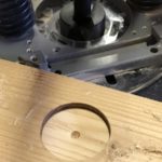
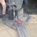
At that point our progress came to a screeching halt when I realized that the Forstner bit’s 3/8″ shank (the bit creates a flat bottom hole) was not going to fit the Bosch’s 1/4″ or 1/2″ collet. Argh! So off to three stores we went in the rare chance that they might have the collet we need. Sadly they didn’t and more sadly the clerks didn’t even know what a collet was (the collet holds the bit tight).
Oh well… Amazon to the rescue. Ordered and it was on it’s way for next weekend.
June 16th
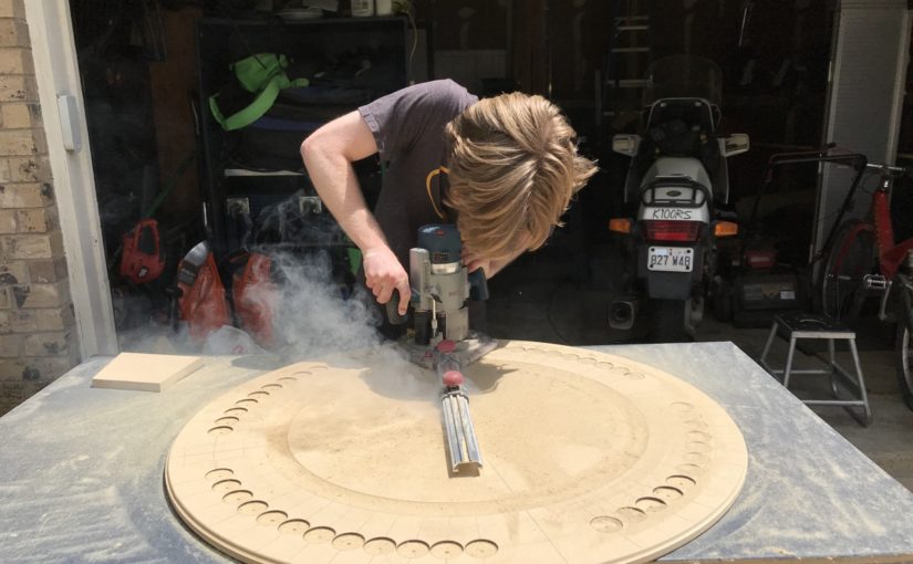
With the collet in hand and a test hole made we set up again and started cutting the poker chip holes.
Something to note… Forstner bits, like most drill bits, are designed for much lower speeds than router speeds. In this case the minimum router speed is 8,000 RPM vs. 600 RPM used on the drill press. You’ll notice the smoke in a pic or two as the bit heats up as well as the blacked edges of the holes as a result of the much higher speed. Could we have used the drill press? Yes. But it would have been much more difficult and resulted in less accuracy in placement. By using the router with the circle guide the placement of the chips on the circle was guaranteed. We simply had to focus on the distance between chips. One dimension rather than two.
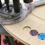
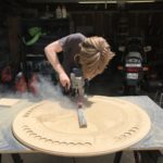
48 flat-bottomed holes and a very hot bit later, we had a place for every chip! It was starting to come together. We added an ogee profile to the outer edge using my trusty 20+ year old Porter-Cable trim router. (There’s a real satisfaction of using a tool purchased before my able helper Ben was born.)
An additional 4 flat-bottomed holes were cut for the neodymium magnets used to hold the poker hands in place on the “table”.
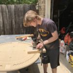
Ben through-drilled the centers of each chip recess to allow for pushing the chips out from the back of the clock with a small drill bit or Allen key.
The next step required making a simple jig. We glued up a few pieces of MDF with an opening just slightly larger than a playing card. Using the Porter-Cable with a pattern-cutting (top-bearing) bit, recesses were made for the quarter hour positions about 1/8″ deep.
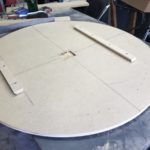
We flipped the clock face and made a recess for the clock movement as the movement’s shaft was 3/4″ – the same thickness of the MDF.
How does one hang such a large and heavy piece? Good question. I choose a French cleat. It’s a strong, simple, and reliable system.
With the millwork done we installed the magnets and used epoxy to fill in the gap and level out the clock face.